Design: VoltMeister 100, a DIY Bench Power Supply
As an electronics hobbyist one of the most essential tools is a bench power supply. I don’t have one yet, so I’m currently stuck with using simple wall warts. This is fine for powering an Arduino, but it gets more tacky when dealing with things like op-amps.
Because I only have limited experience with Arduino and a rudimentary understanding of electronics, I decided not to make my first project about using 230VAC directly and creating an adjustable power supply. Instead, I opted for a more common approach: use an existing ATX computer power supply to deliver the four common output voltages of these supplies: 3.3V, 5V, and ±12V.
The ATX Power Supply
Modern computers all comform to the ATX standard, set by Intel in 1995. Part of this standard is the power supply. ATX power supplies are easily available and interchangable.
Older models ATX power supplies have a 20-pin connector, new ones have a 24-pin connector.
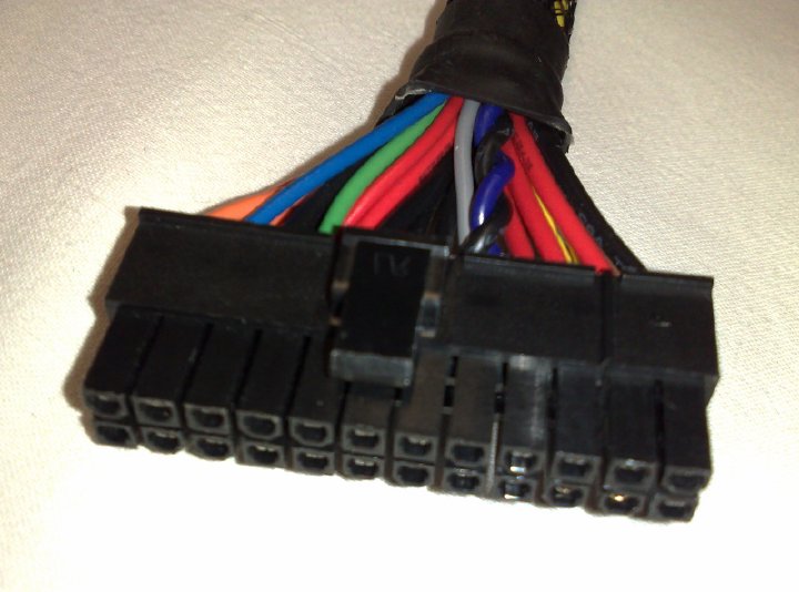
The 24-pin configuration adds four pins, one for each supply voltage and GND (Ground). A 20-pin connector does fit a 24-pin socket. Yay for standards!
An ATX power supply offers a total of four voltages. However, they each have different power ratings. There’s probably a sticker on your supply telling you the exact details.
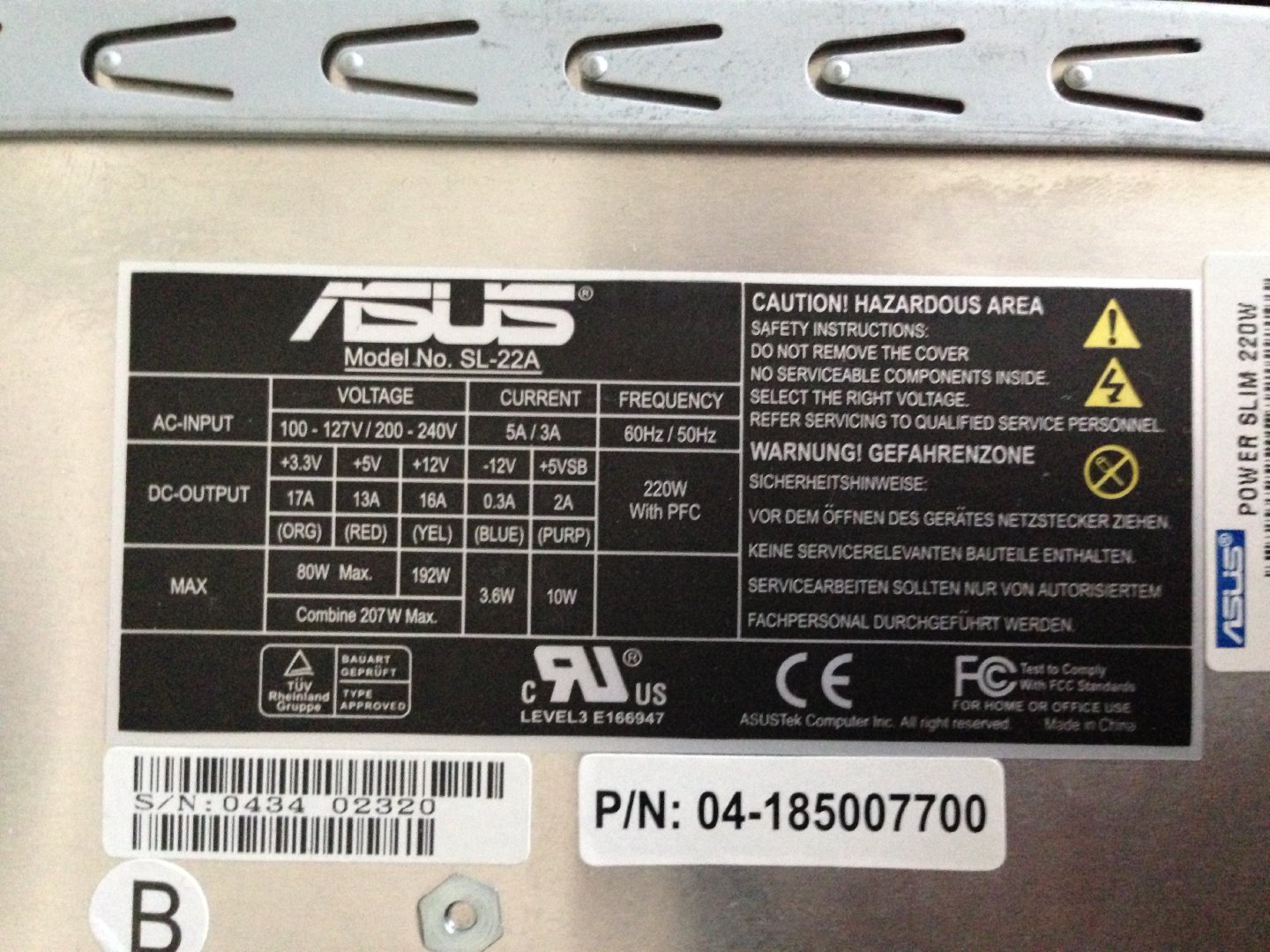
The supply I’ll be using in this project comes from an old Asus S-Presso. As the label indicates, it can supply different voltages with different power ratings:
- 3.3V at 17A
- 5V at 13A
- 12V at 16A
That’s quite beefy (except the -12V), especialy if you’re mostly toying around with microcontrollers and microprocessors.
There are also two other notable voltages. -12V and 5VSB.
The -12V is ideal if you’re doing things with op-amps that need a positive and negative reference. But, as you can see, the -12V rail only supports up to 0.3 amps. This means you can’t combine the ±12V rails to create a 24V output that draws lots of current.
The 5VSB provides 5V at a maximum of 2A when the power supply is on stand by. When you have the power supply plugged into mains, but it’s not running, the power supply still delivers 5V over this stand by line! Your computer normally uses this to wake from sleep and such things.
Design goals
I’ve set the following design goals for the VoltMeister 100:
- Use a small-size ATX power supply (Asus SL-22A)
- Output 3.3V, 5V, 12V and -12V
- Show stand-by and power-on conditions
- Limit output current to 2.5A
- Build a nice enclosure so it can sit on my bench :-)
The ATX power supply does a good job of limiting current and shutting down in short-circuit situations. However, 16 amps on 12V is quite a lot of power and will probably cause a lot of ICs to release their magic smoke. Since there is nothing I can think of right now that’d need more than 1 amp from this supply, I’m want to limit the output current the somewhat safer level of 2.5 amps (for each voltage).
ATX Connector Pin-out
ATX Power supplies have a 20-pin or 24-pin connector. These are compatible connectors and the 20-pin connector fits the 24-pin connector.
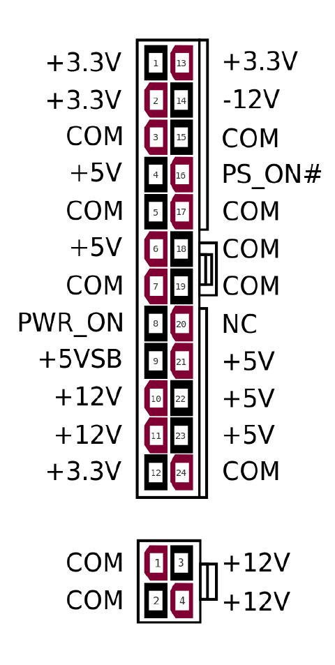
Let’s walk through these quickly. All COM pins are common ground and can be used
with any supply voltage.
- Pins 1,2, 12 and 13 provide 3.3V
- Pins 4, 6, 21, 22 and 23 provide 5V
- Pins 10 and 11 provide 12V
- Pin 14 provides -12V
- Pin 9 provides 5VSB, always available when the supply is connected to mains
- Pin 16 is the power switch, connect it to GND to turn the supply on.
- Pin 8 (PWR_ON) supplies 5V when the power supply is on and providing stable voltages.
- Pin 20 is marked as not connected. In the past the ATX spec placed an optional -5V here, but has since been removed all together. Don’t rely on -5V to be available.
The most important thing to note here is the PWR_ON pin. It supplies 5V when
the supply is providing a stable output. PWR_ON does not come on instantly, as
it takes some time for the ATX supply to stabalize. Although this process is quite
fast, there is a noticable delay of about half a second between switching the supply
on and the PWR_ON going high.
Schematic
All the hard work of converting mains 230VAC to a more suitable 3.3/5/±12V is done by the ATX supply. The only custom things left to do are:
- Accept a 20 or 24 pin ATX connector
- Provide a connection for the power-on and standy-by LEDs
- Provide a connection for a power switch
- Provide connections for 3.3/5/±12V outputs and GND
- Limit current to 2.5A for each output voltage
The schematic for this is rather straight forward:
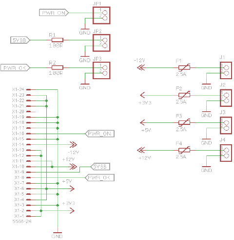
The power LED is directly hooked up to pin 8, PWR_ON with a series resistor to limit
the current through the LED and make it not annoyingly bright. The same goes for the stand-by LED.
The power switch is directly connected to pin 16 and GND, pulling pin 16 low when switched on.
The four output voltages, together with GND, are routed to output pins so they’re easy to hook up to the actual banana sockets in the case.
Each supply voltage is fitted with a 2.5A resettable fuse (or PTC). Anything up to 2.5A is fine, above that the fuse will start to act as a circuit breaker. When the faulty situation is resolved, the PTCs will reset and you use the supply again.
Note: you may notice there is a 2.5 amp PTC on the -12V output. That’s weird because the power supply limits this voltage to 0.3amps anyway. Keep in mind that other power supplies may be rated for higher current on the -12V rail and will need this PTC to keep me safe.
PCB
Because the ATX connector (MOLEX 39-28-8240) uses a 4.2mm pitch spacing it does not fit on a protoboard. So, let’s design a PCB! Here’s my the C revision of my PCB design:
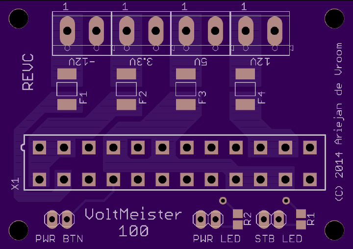
I’ve created wide traces for the supply voltages, as up to 5A needs to be able to flow through them. (5A is the trip-current of the PTCs). Each voltage, together with GND is exposed through screw terminals. There are pinheads for the LEDs and the switch.
I’ve opted for SMD parts because I wanted like to give SMD soldering a try.
Lesson learned
- ATX power supplies are easy to work with, but also quite powerful. Be very careful if you open one up.
- I should mark the +/- for the LED and terminals more clearly
- Consider the connection points on the PCB, it turned out that it would have been easier if the LED/Button connections were on the same side as the voltage output terminals.
The enclosure
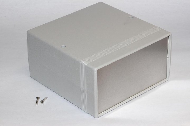
I think that in a professional design process there is some tension between the PCBs you design, the components you use and the enclosure you need to all fit it in. I tried to be smart and opted to buy a ‘universal enclosure’ that would fit my ATX power supply and leave some room for a small PCB.
Because of the dimensions of the ATX power supply (roughly 140x50x80mm), I needed something that would fit that. Note that most dimenstions specified when shopping for enclosures are outside dimensions.
In the end I opted for a nice Hammond enclosure, large enough to fit my power supply snugly and not too expensive. It even has nice aluminium front and back panels. For those wondering, it’s the 1598ESGY from Hammond.
Another thing I learned is to take a detailed look at the specification drawings.
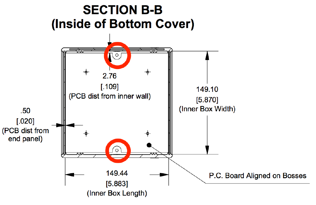
Notice the two supports circled in red? Yeah, those are used to screw the top and bottom parts of the enclosure together. And guess what, my ATX power supply does not fit between those two supports and is now protruding about 10mm from the back. Booh!
This is really a problem. I don’t want to have an ATX power supply hanging out of the back.
At first I thought of just buying a larger case, but I would not be that easily defeated.
Because I’m curious by nature, I opened up my ATX power supply to see what’s inside and remove some of the cables I would not need.
The PCB for the ATX supply is pretty tightly packed, but I noticed that transformer on the side was not mounted on the PCB. There was a nice cutout on the PCB to allow room for the transformer.
Putting one and one together I decided to remove the ATX enclosure and see if I could fit the PCB in my small Hammond case. The transformer could be moved just a bit so it would not interfer with the support inside the case.
This worked brilliantly. All I had to do was make cutouts for the powercord and 120/230V selector.
The only reason I did this is because there is a clear separation between the high voltage parts of the supply and the control (for the fan, I presume). Because the orientation was just right, it would also shield my own PCB nicely.
The build
Here you can see the inside of my bench power supply.
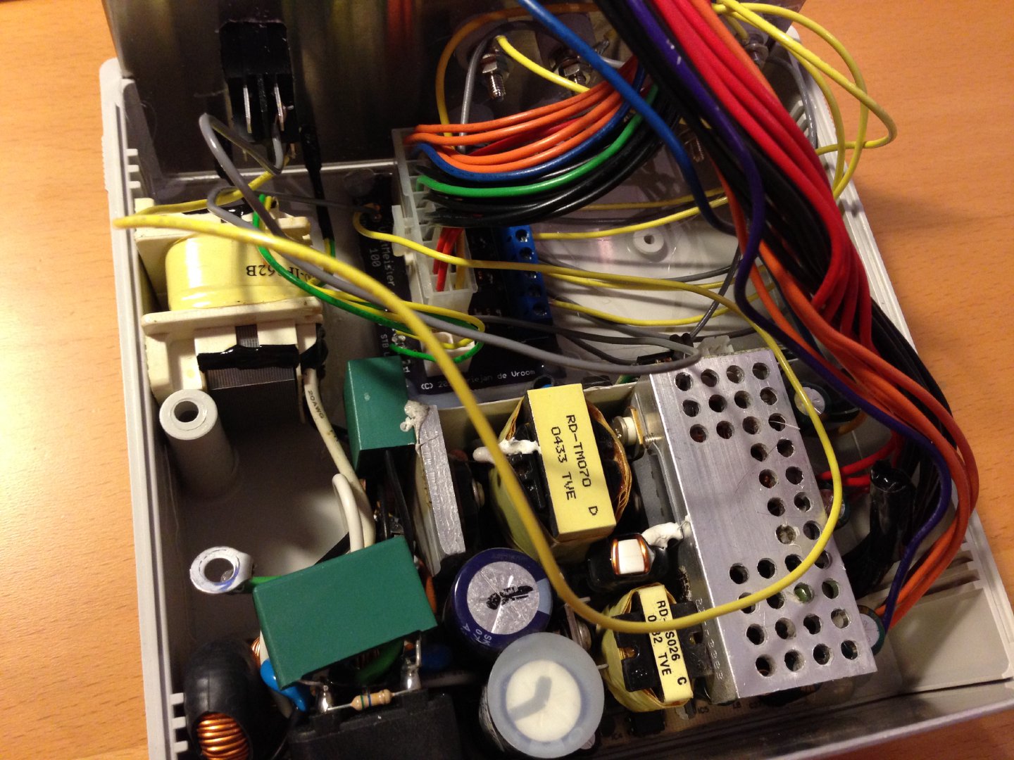
The bottom half is filled with the ATX PCB. You can see the ground wire floating around, this has been connected properly tot he front and back panels.
The transformer is leaving a bit of a gap and has been placed just on the other side of the support.
On the top you can see my PCB with the ATX connector attached to it and wires going out to the LEDs, the power switch and the different output voltages.
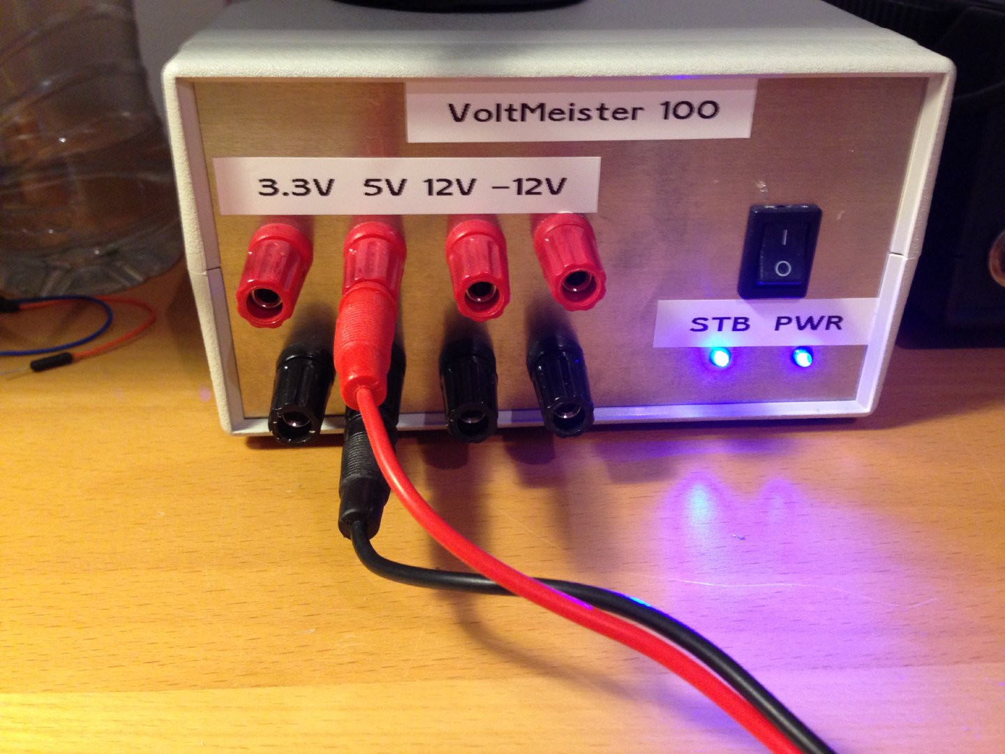
The result
And, this is the end result. Suffice it to say that my precision drilling skills need some more love. But other than that, I’m quite happy with how it turned out. It’s my first project, after all.
Conclusion
Building an ATX-based bench power supply like this is nice. If you need a stable and reliable power supply, you’re probably better off buying a cheap linear power supply online for like € 50.
I did this project to learn something. And I did. I learned how to SMD solder components, I learned what to look out for when selecting an enclosure for your project. I also learned about ATX power supplies and how you don’t want to mess with them. These units handle pretty beefy currents. If you don’t know what you’re doing you could end up hurting yourself.
What’s next? The VoltMeister 200, of course!