Repair: Philips 42" 3D LED TV with Ambilight
I’ve done the occasional television repair in the past. Mostly Philips TVs with the ‘3 blinks’ problem. When the power supply of a Philips TV is defective, the main board will detect this and blink the stand-by led 3 times to indicate this problem. Power supply issues I can fix - mostly.
So, I found this Philips 42PFL6057H/12 TV on Marktplaats. Instead of the ‘3 blinks’, this TV did absolutely nothing. Another clue that the power supply is probably toasted.
Step 1 - Open it up
First thing is to remove the back cover of the TV. There are a dozen or so screws on the back. These, together with two cables for the buttons and ambilight, expose the power supply board and main board.
The exact workings of how a Philips TV boots up when power is first connected is a bit more complex than what I’ll describe here (read the service manual if you’re interested). When the power cord is connected, the power supply will generate a 3.3V stand-by voltage. This is enough to power the ‘Fusion’ chip on the main board. The main board will then signal the power supply to start the 12V rails.
So, the first order of business is to check if the 3.3V is there. It wasn’t. Careful probing revealed a shorted dual-diode package. Luckily, I was able to replace this part, as another power supply board from a previous repair had a similar dual-diode.
This brought back the 3.3V, but now I did get the 3 blinks, as the power supply was not able to provide 12V. Some further investigation revealed that one of the control ICs on the power supply board seemed damaged as well. This part is hard-to-get and I opted to purchase a replacement power supply board.
Step 2 - Why won’t it work!?
With the power supply board replaced, I could measure 3.3V and 12V from the power supply. However, the stand-by LED wouldn’t turn on. The TV would respond with a blinking LED when I used the remote control on it - but it would not turn on.
Some googling revealed that this is a main board defect and can’t be repaired. It’s recommended to replace the main board.
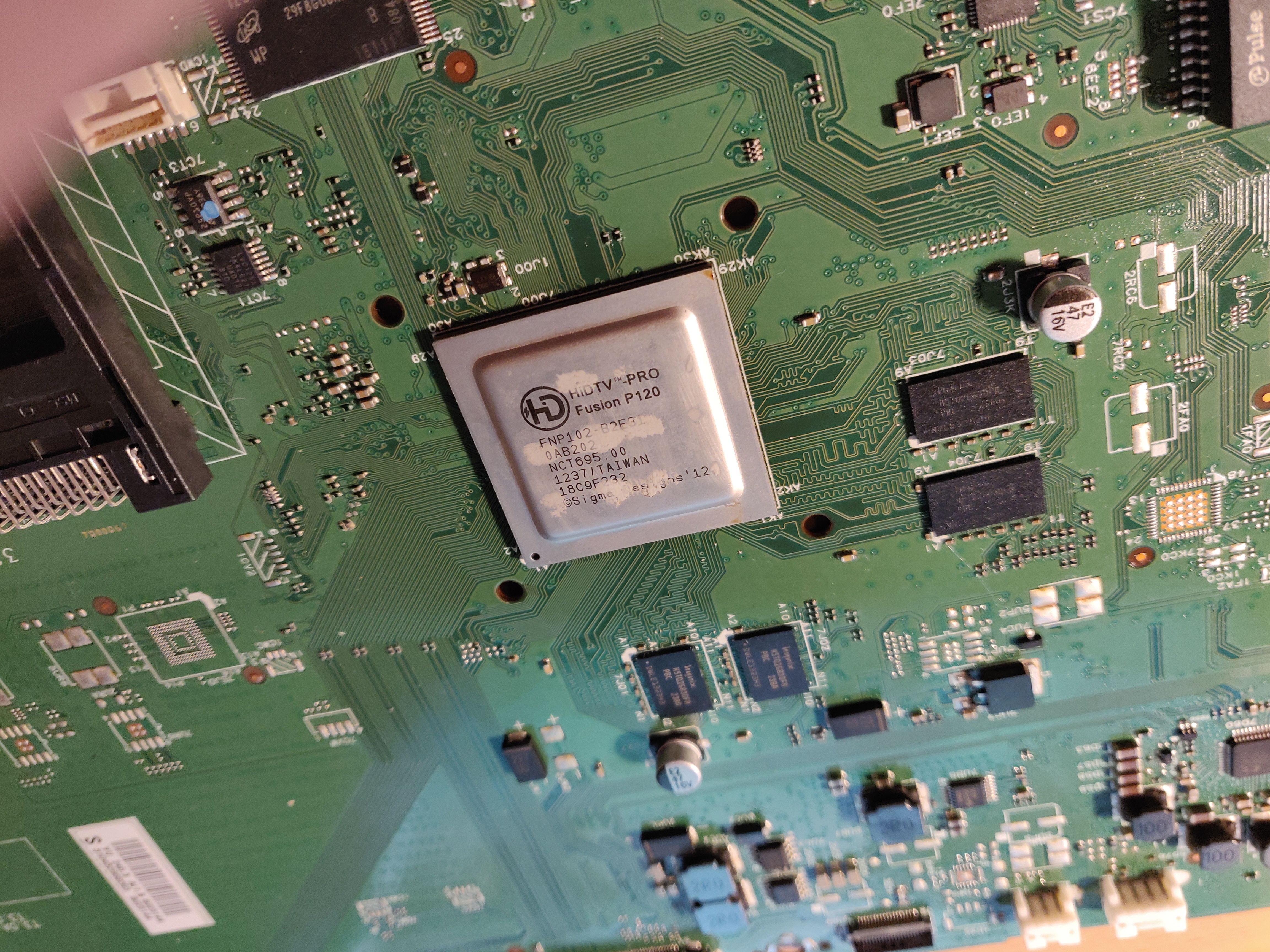
Well, I already replaced the power supply board, and I really didn’t want to add further costs to this repair. Looking at the main board, it’s not very complicated. There are some peripheral connectors and support ICs, an audio section, and this big BGA Fusion SoC. It’s heatsinked on the front. On the back a piece of thermally conducting foam was used to sink some heat into the metal chassis of the TV.
So - nothing is obviously burnt. The TV does power up (so the Fusion SoC must be doing something), but it won’t turn on.
If there were to be a problem, my guess would be that the Fusion SoC suffered some thermal stress and any one of the BGA connections might have been damaged.
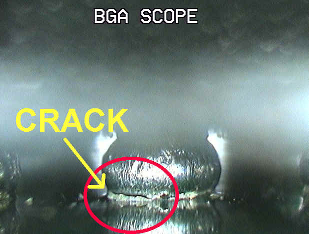
BGA (Ball Grid Array) is quite simple. The IC and PCB have solder pads and you sandwich small balls of solder between them to make an electrical connection and secure the IC in place. This works great for SMD assembly of ICs with a high pin count.
One problem is thermal stress. When the IC generates heat, the PCB expands - and shrinks again when it cools off. In the long run this may also cause stress to the miniscule solder balls.
I found this photo on the internet that shows the exact problem. I don’t have the equipment to inspect BGA’s like this.
Step 3 - Reflow
At this point the main board is unusable. I can either replace it or attempt to fix the possible solder ball issue I suspect.
Feeling adventurous, I removed the main board and powered up my heat gun. I have one of those (cheap-ish) soldering stations that come with an old fashioned iron and hot air. I removed the heat sink and started carefully heating up the IC. I tried measuring the surface temperature of the IC with my infrared meter, but I did not measure above 160°C - too low to melt solder. Then I noticed that the solder on nearby resistors did melt.
I stopped heating the board and let it cool for a few minutes. Re-installed the board and all the cables. Plug in the power. Press the power button. And there it was. A working TV.
Step 4 - Cleaning up
The ceramic heatsink on the Fusion SoC was attached with adhesive heatsink tape. It didn’t stick. Luckily there were mounting holes around the IC, so it was easy enough to construct something to keep the heatsink firmly attached.
Next, reinstall the back panel and reconnect the Ambilight cable. And I’ve got a new TV :-)
Update 2019-03-29 about a year later the TV failed again. Read all about it here
