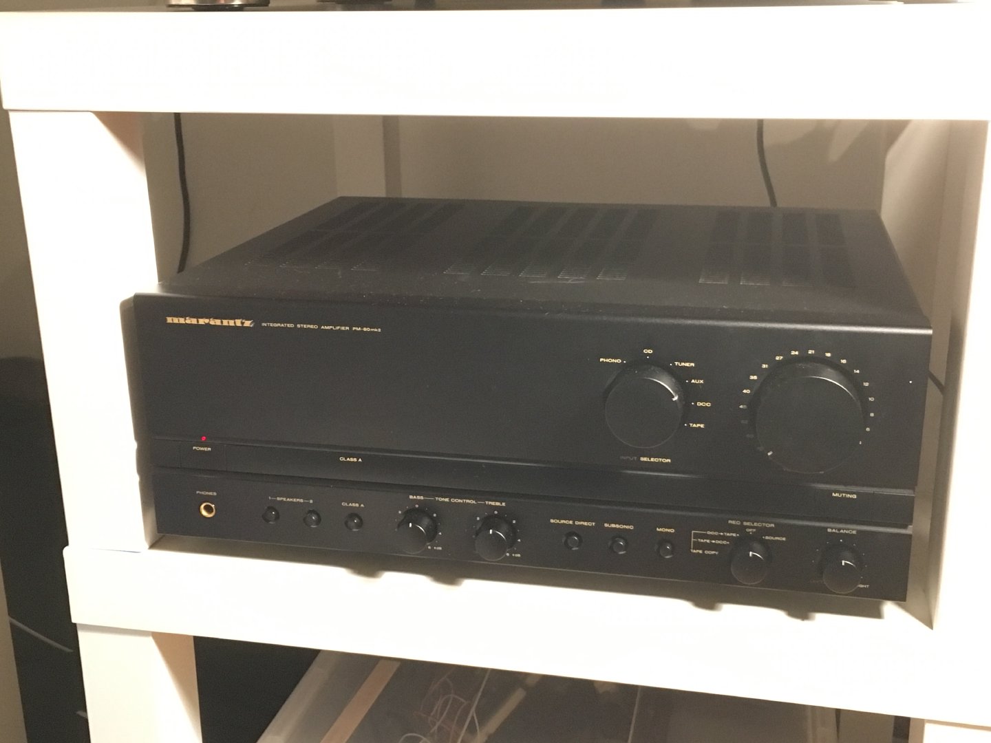
Repair: Marantz PM80 Mk2
The Marantz PM80 Mk2. The Hi-Fi connaisseur knows what I’m talking about.
The amp sounds amazing when in Class AB mode (100Wpc), but it can also be switched to Class A mode (25Wpc) for intesive listening sessions with even lower distortion. \m/
This unit was defective: it did not work at all. The power light would come on, but nothing else.
Note that this is a MkII model. The MkI and SE models have a STK amplifier IC that tends to break often, but no replacment is readily available. The MkII does not have this STK module, so there’s that.
Diagnostics

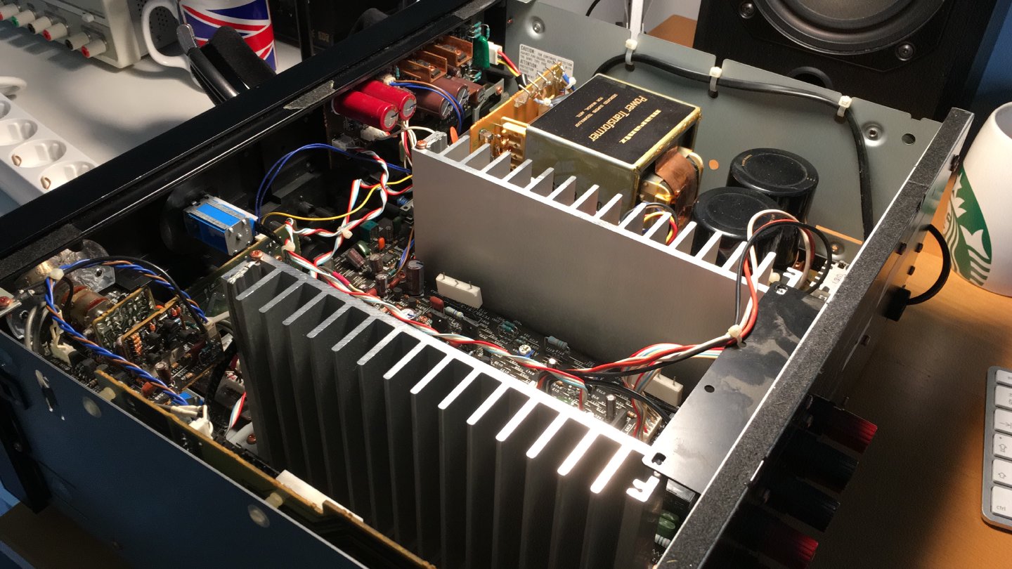
First a visual inspection. There’s a huge power transformer and two very large capacitors. The power FETs are mounted on two separate heatsinks.
A quick look around reveals nothing out of the ordinary. No burnt parts, not buldging capacitors, no blown fuses. Time to turn the volume to 0 and turn it on.
After powering on the amp, nothing happens. The power LED comes on, but that’s it. Normally I’d expect to hear the speaker relays click - but they didn’t. If one didn’t click, that might be a mechanical failure of the relay. Both not clicking means there’s something wrong.
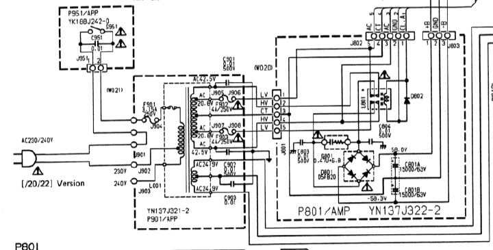
Time to grab the multimeter and do some measurements. First, the mains input and
transformer board. This is the /22 model. All inputs and outputs measure good voltages.
Because the speaker relays are not clicking on, I measured the outputs (on the PCB) for DC voltage. Ideally, speaker outputs should measure 0V, but nothing being perfect, a few mV of DC is okay. Anything above 0.1V should be considered a fault, however. I measured 0.33VDC - not good. The protection circuitry detected the DC voltage and kept the relays off to protect any attached speakers.
So, why is there a DC voltage on the outputs? This could be for a number of reasons ranging from failed components, bad solder connections to a failed power supply.
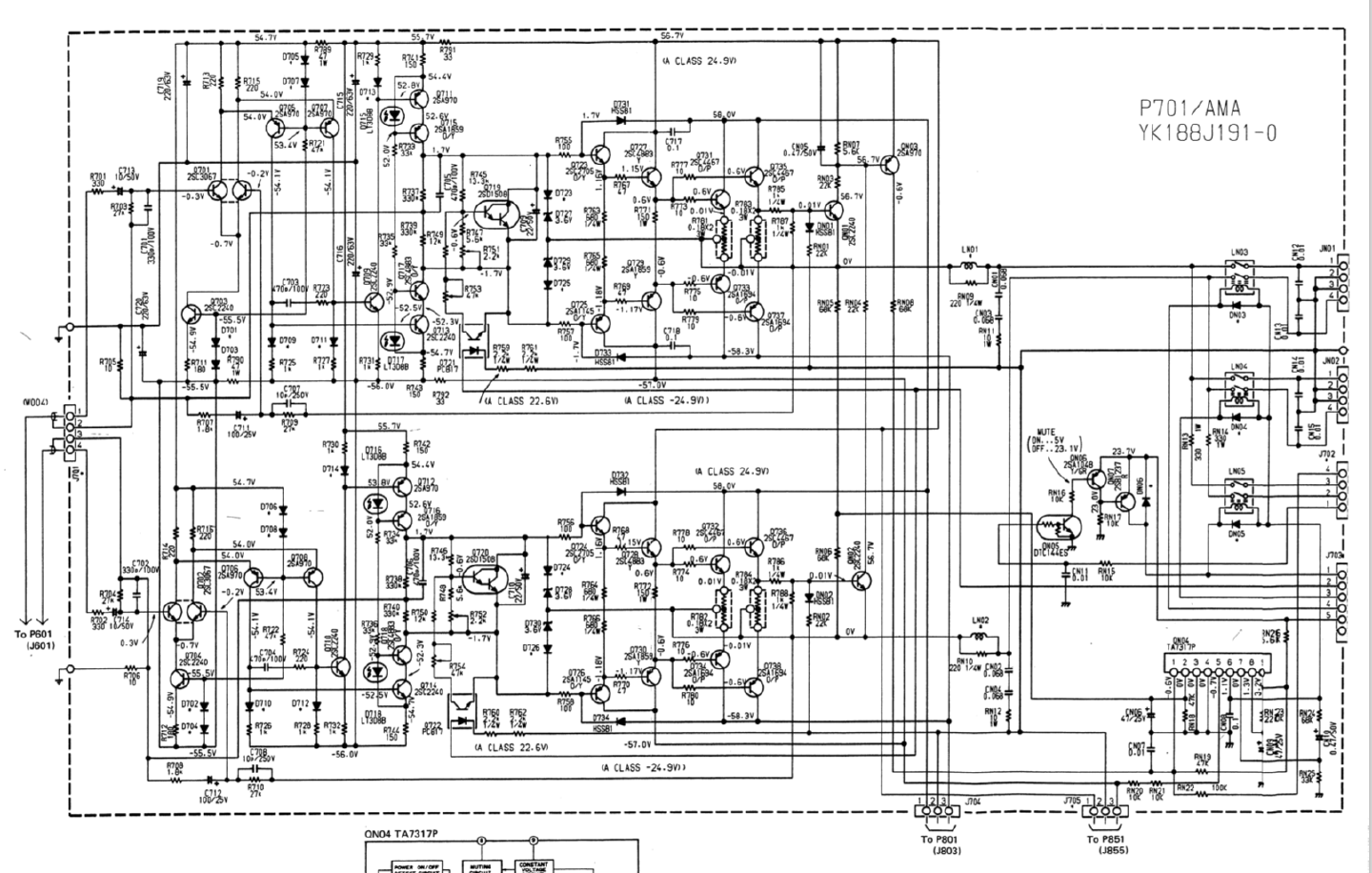
I worked my way back from the speaker terminals through the schematic, measuring the voltages mentioned. I quickly discovered that the ±57V (from J705) were too low: 1.1V and -0.14V. J704 comes directly from the transformer board with ±60V, but J705 comes from a separate power regulator board.
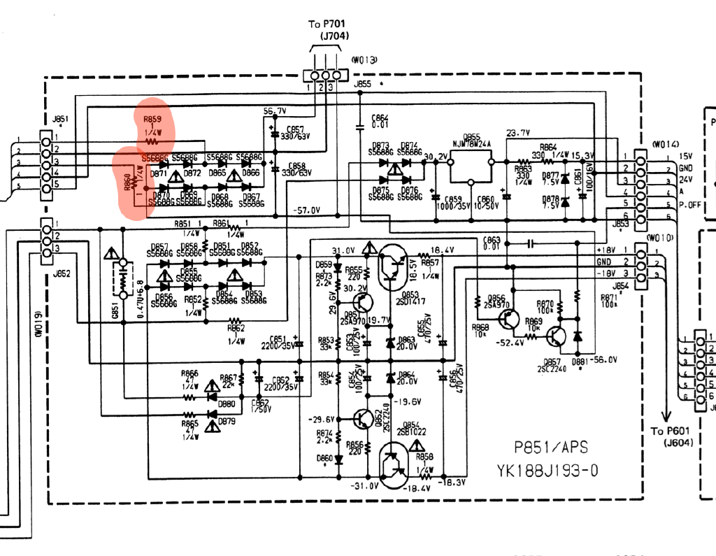
Because the input AC voltages (J851 1-3) looked all right, but the DC voltages (J855) were way too low, the problem should lie between those points.
Capacitors C857 and C858 appeared in good working condition (no damage, leaking, buldging). All diodes (D865-D872) measured at a nice 0.6Vf.
Resistors R859 and R860 measured in at 2.3MΩ and 163kΩ respectively.
Wait a minute. Those should measure at 1Ω. Whoops.
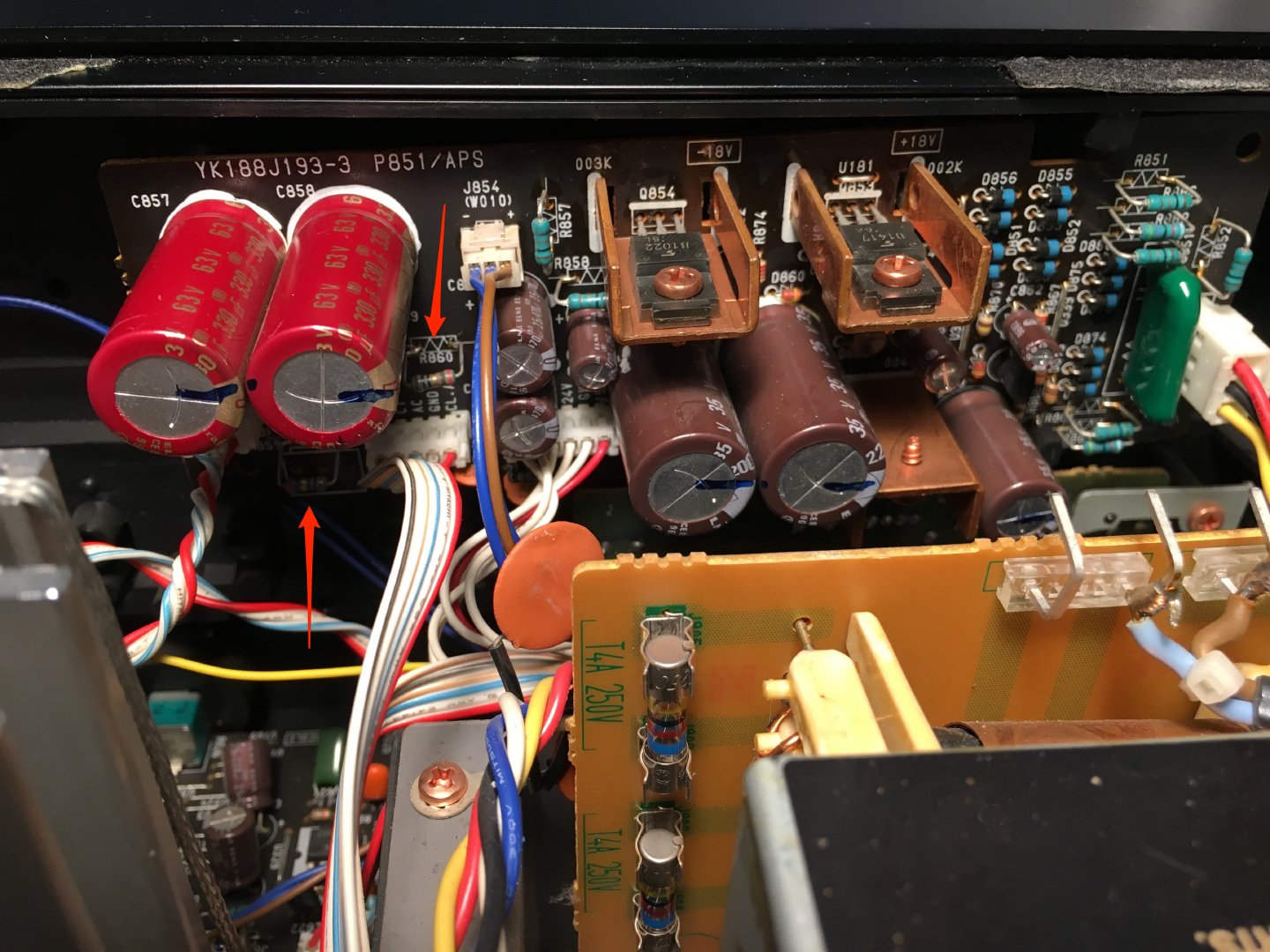
The resistors don’t seem to have failed catastrophicaly, going out in a blaze of magic smoke. Instead, they seem to have failed from a longer period of intensive use.
Repair
1Ω 1/4W resistors are something I have plenty of. Replacing them was very easy as the regulator board is snapped in by two plastic holder pins. Removing and replacing it was easy.
With the resistors replaced, the output is back to ±57V and the speaker relays click into actions when powering on the amp.
Moment of truth: connect testing speakers and an audio source. Slowly turning up the volume. It’s back in action!
Although I like the Pioneer VSX-921-K I’m currently using (especially the AirPlay feature), it pales in comparison to the sound quality of this monster. It’s a great match for my Sennheiser HD650’s as well.
So, this is a keeper :-) I’ll build some DAC/AirPlay device myself, but the PM80 stays. ♥️
Notes
The service manuals for the Marantz PM80 are available for free at hifiengine.