Design: Phono X, a RIAA Phono Preamplifier

When I started out designing this preamp I only had a few requirements:
- Perform RIAA equalisation and pre amplification for a Moving Magnet (MM) cartridge
- Connect my Technics SL-3310 to my Denon AVR-2113.
- Sound decent (e.g. no 50 Hz hum, etc.)
- Directly powered from 230VAC
Searching the internet yielded quite a few pre-designed phono preamp stages. The main issue I had with most of them is the sheer amount of customization put into each design. Take the Muffsy for example. The Muffsy tries to accomodate many different cartridges by making input impedance and gain configurable. This is great, but I just have one turn table. I might get another one in the future, but I’m pretty sure it’s going to be mainstream moving magnet again.
I also found Elliot Sound Products’ Project 06, a Hi-Fi Phono Preamp with RIAA equalisation and good reviews.
With all the different designs in the back of my mind, I started out designing Phono X.
The power supply
The power supply is normally the last thing I design. When everything else is finished, I have a clear picture of power supply needs. Because the main components are a pair of OPA2134 opamps, I want to have a clean ±15VDC power supply. The OPA2134 can be supplied with up to ±18VDC, but ±15VDC seems more than adequate for the job. ±15VDC is also what Elliot recommends in his design.
So, to get a clean supply voltage, I opted for an almost classic linear power supply, using a 20VA 2x 15VAC toroidal transfomer.
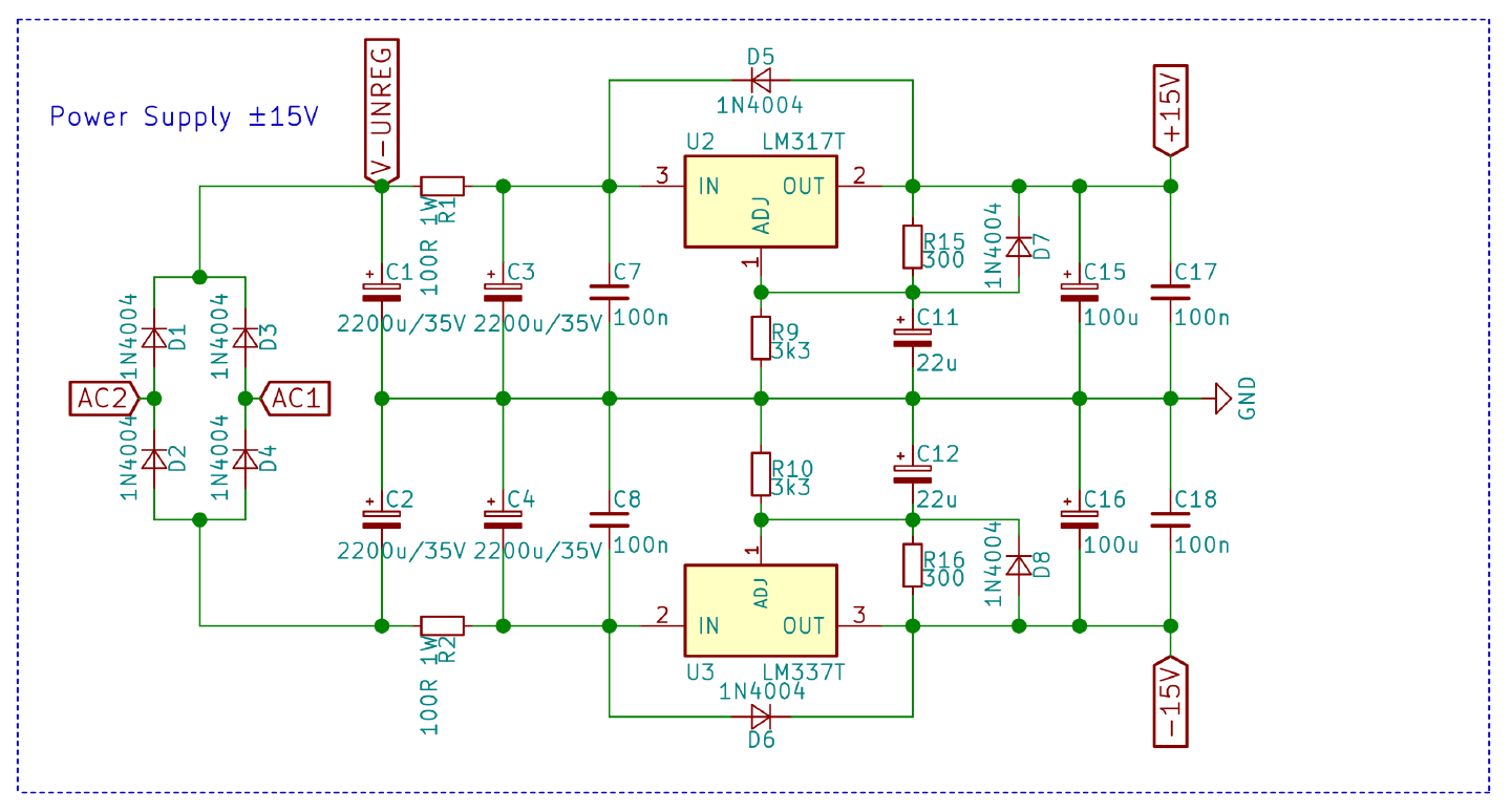
AC1 and AC2 are connected to the transformer. The D1-D4 diode bridge rectifies the AC
into DC which gets filtered by the capacitors C1-C4. Next is a +/- pair of an LM317 and LM337
to regulate the voltage to ±15VDC, including protection diodes.
Pre-amp circuit
Below is left channel preamp circuit, the right channel is identical. Most notable detail is the OPA2134, which is a dual channel opamp. One unit is used for L+R RIAA equalisation and another unit is used for amplification.
This is almost an exact copy of Elliot Sound Products’ Project 06 design with a few small tweaks.
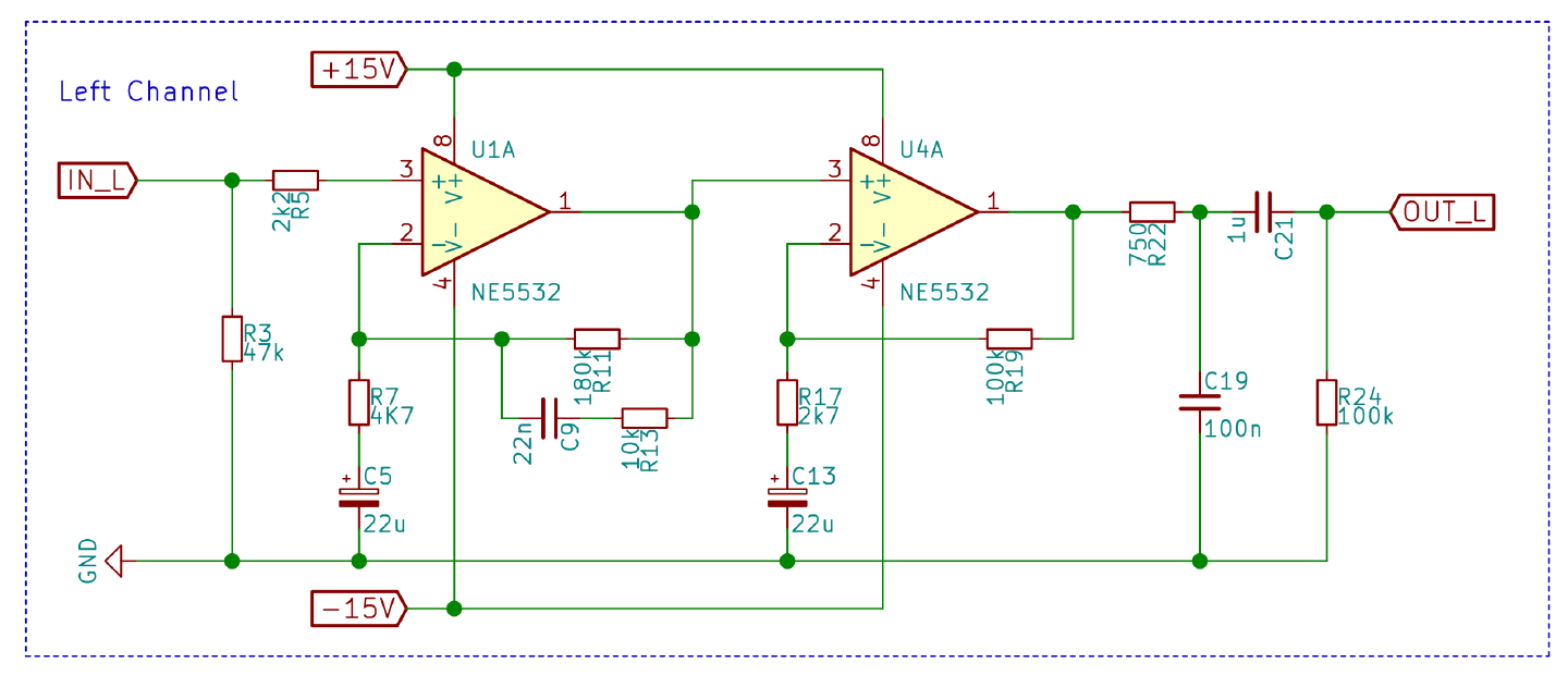
- I omitted the
CLLandCRRcartridge loading capactiors. - For
C19andR22I used 100nF and 750Ω instead of the specified 82nF and 820Ω, as per ESP’s instructions. - The 10uF and 100nF by pass capacitors for the opamps are omitted in favour of
C15-C17in the power supply.
PCB Design
This is the final PCB design. In retrospect I should have better divided the available board space between different functions. Power supply and preamp are a bit mixed up. Also, the signal traces for the right channel are tad longer than left. I’m not sure this results in an audible difference, but it still doesn’t feel right.
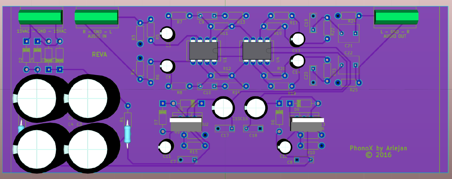
The width of the board was chosen to fit in the pcb brackets of the enclosure.
Retrospective
So, what did I learn doing this build?
- There’s (presumably) a considerable inrush current into the big
C1-C4capacitors. When the amp is already powered up, switching on the Phono X will cause a not-so-nice popping sound. I should probably add some soft - When powering off, the capacitors keep the amp working for quite a while. It might be nicer to really shut down the output when turning off.
- Transformers affect signals. Keep them away from signal traces or maybe use some sort of shielding.
- Add the recommended Project 99 Subsonic Filter to prevent sub 20Hz noise coming through.
- Get the right equipment to measure performance of my build myself ;-)
- Use a more symetrical design for the PCB, and maybe split the power supply and signal boards into two separate boards.
Datasheets
- OPA2134 High Performance Audio Operational Amplifier